Overview
The requirements for today's high-speed, high-bandwidth communications systems are constantly expanding with more diverse platforms and unique environments. At the same time, smaller, lighter, more efficient packaging is being demanded to allow designers to pack more into less space.
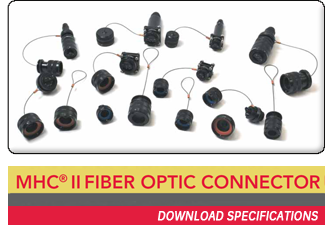
OCC's Mini Hermaphroditic Fiber Optic/Hybrid Connector (MHC II) fills that requirement. The MHC II is designed specifically to inter-connect fiber optic channels in a small, yet effective, package. Using a bayonet-style, mechanical coupling interface, the plug connector is easily mated to receptacles by a simple twisting motion.
The MHC II 8 CH Connector system provides maximum flexibility by allowing many combinations of fiber optic termini and electrical contacts to coexist within the same hermaphroditic connector system.
The MHC II fiber optic termini feature both pin and socket configurations to accommodate 62.5/125μm, 50/125μm, 9/125μm single-mode/multimode fiber or a combination of fiber types depending upon cable construction requirements and are available in 2-, 4-, 6- and 8-CH versions. Since the connectors are hermaphroditic, two plugs can also be mated together using the same bayonet feature, allowing for end-to-end mating of multiple links, making deployments quicker. The MHC II series hermaphroditic connector incorporates proven 1.25mm ceramic ferrule technology to achieve excellent mating durability with excellent insertion loss performance that is on par with the OCC family of connectors. The MHC II family of connectors is available in various plating/base materials to match application needs, including nickel-teflon, black anodized, marine brass and stainless-steel.
Applications
- Voice/Data/Video in Harsh
Environments
- Deployed Broadcast Systems
- Remote Monitoring Sites
- Robotic Arms and Robot
Devices
- Industrial Monitoring
Provisioning Guidelines - Fiber Optic Only
- Select the appropriate shell size to accommodate the fiber optic channel count. Shell size A allows two channel and four channel. Shell size B allows six channel and eight channel.
- Select the connector configurations that meet the intent of the application. All plugs are hermaphroditic and feature an integrated backshell. Receptacles are selected based on jam nut, flange-mount or flange-mount with strain-relief receptacle options.
- Identify the number of termini required to support the fiber count.
- Jam nut or flange-mount receptacles utilize termini that only accommodate 900μm tight buffer fiber optic cable. Flange-mount strain-relief receptacle (srr ) utilizes distribution- or breakout-style cable and provide additional pull strength for simplex connector pigtails.
Provisioning Guidelines - Hybrid ( Combination of Electrical and Fiber Optic)
- Select shell size B to accommodate combination of fiber optic and electrical channels.
- Select the connector configurations that meet the intent of the application. All plugs are hermaphroditic and feature an integrated backshell. Receptacles are selected base on jam nut, flange-mount or flange-mount with strain-relief receptacle options.
- Identify the number of fiber optic termini and electrical contacts required to support the application. Two fiber, six electrical – V-Series (2f+6e), four fiber, four electrical – T-Series (4f+4e), six fiber, two electrical – W-Series (6f+2e) are available. There are additional configurations for each of the shell sizes with the use of dummy termini, which provide greater flexibility in provisioning.
- Jam nut or flange-mount receptacles utilize termini that only accommodate 900μm tight buffer fiber optic cable. Flange-mount strain-relief receptacle (srr ) utilizes distribution- or breakout-styles of composite cable and provide additional pull strength for simplex connector pigtails.
|